
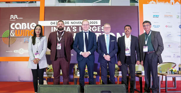
The technical session “Smart Manufacturing: Technology and Material Science Behind Cables” held on November, 05 at CWF25 featured presentations by Mr. David Costabile (MFL Group), Mr. Xander Pierik (Borouge), Mr. Michael Biller (Mikro Diamond Tools), Mr. Ranjit Balachandran (Shakun Polymers), and Mr. Suren Shah (Shakun Polymers). The session examined energy efficiency in extrusion, advanced material behaviour, degassing science, wire drawing precision, and high-voltage compound development, highlighting how manufacturing technology and material science jointly shape cable performance, sustainability, and reliability.
Watch: Top Cable Companies in India

Mr. David Costabile, Area Sales Manager, MFL Group
Mr. David Costabile talks about the energy consumption in the wire and cable machineries, especially extrusion machineries and provides patented solutions like EXA and EXB extruders, along with extrusion screw profile to help cable and wire manufacturers minimize energy consumption.
He begins by addressing that there has been increasing regulation on energy use and motor efficiency in India, promoting industrial decarbonisation through national programmes like ‘Perform, Achieve And Trade.’ and the ‘Net Zero 2070 mission.’ These initiatives encourage manufacturers to adopt energy efficient machinery that helps lower emission and improve overall performance.
He says,‘‘Energy represents a large part of extrusion lines. Sustainability goals, and energy efficiency helps meet corporate ESG targets and reduce carbon footprints. Cost saving is another target for companies. Making energy efficient equipment is not just a cost saving choice, but a step towards regulatory compliance.’’
Talking about the extrusion line, he cites that in the extrusion line, the primary sources of energy consumption are the barrel heating system and the screw drive. Maintaining the barrel at the required process temperature demands significant energy, and the motor driving the screw is another major consumer, especially when operating at high torque and speed. In addition, downstream equipment—such as cutting, cooling, and accumulators—as well as ancillary systems like vacuum pumps and air compressors, also contribute noticeably to overall energy use.
Another factor that affects energy efficiency could be the material that the manufacturers are using such as halogen free flame retardant (HFFR) compounds or low smoke zero halogen (LSZH) compounds that often require higher temperature and longer residence times, increasing the consumption.
These compounds fall under the high friction materials category. They are halogen-free and self-extinguishing types used for conductor insulation or for the filling and sheathing of multipolar cables.
Line configuration also impacts energy consumption. Factors such as whether the line uses a single-layer or multi-layer setup, as well as the machine’s age and maintenance condition, play a significant role. Older machines generally operate less efficiently due to outdated motor controls and mechanical wear.
Using energy-efficient motors—such as IE3 or IE4 class motors—along with frequency inverters significantly improves overall efficiency. Enhanced barrel insulation, including thermal insulation jackets, helps reduce heat loss and maintain stable process temperatures. Advanced temperature control systems with PID control and smart heating zones further minimize energy waste. Optimizing vacuum degassing through sensors and intelligent control systems ensures effective venting while avoiding unnecessary energy use. Regenerative drives can also capture energy generated during acceleration and feed it back into the system, contributing to additional savings.
With IoT-based monitoring and digitalization, real-time tracking of energy consumption across each section of the line becomes possible. This level of visibility enables targeted optimization and supports predictive maintenance, helping identify inefficiencies and prevent unplanned downtime.
He further says, with the introduction of strict regulations on cable performance under flame conditions, plastic material manufacturers have significantly increased the use of inert fillers. These fillers help prevent flame propagation and limit plastic dripping during combustion. Due to this change, it has been observed that during the high-speed extrusion process, a large amount of friction is generated, which turns into heat from within the extrusion cylinder. The challenge therefore is to cool the extrusion cylinder effectively to counteract the heating effect caused by friction generated inside the cylinder. ‘‘If, during the extrusion process, the reaction temperature of the metallic hydrates in the compound is accidentally reached, the material will activate prematurely, compromising the cable’s properties. As a result, the cable becomes unusable and must be scrapped.’’
Notably, HFFR, based on aluminium or magnesium, has a very specific working temperature limit behind which the material decomposes, releasing water molecules that delay flame spread. At the same time, the melt temperature must be controlled very quickly so it never exceeds the material’s decomposition point. Even when the line slows down (deaccelerates) or speeds up (accelerates), such as during coil changes in the extrusion line.
He discusses MFL’s patented technology as a solution provider. He says, ‘‘The patented solution adopted in our company is EXB extruder range that is aimed at maintaining the plastic in the best processing condition and achieving high production output. To accomplish this, we have also designed an extrusion screw profile capable of delivering high output at a low rotation speed, significantly reducing shear stress of material.’’
He adds, ‘‘Additionally, our extrusion cylinder features a larger sternum cooling surface and unlike other solutions in the market, the cooling air is forced directly onto the extrusion cylinder, enabling direct cooling without passing through other surfaces.’’ The barrel heating system features a larger sternum cooling surface and cooling air forced directly onto the extrusion bar, enabling direct cooling.
‘‘So, in our machine, the thermocouple is placed directly in contact with the melt, allowing it to detect any temperature change quickly and accurately, eliminating any possibility of delay in reading. We are not only controlling the temperature of the extrusion cylinder, but are also performing melt thermoregulation.’’
In traditional construction, the thermocouple is positioned on the extrusion barrel, away from the melt. This is just to give you an example of the difference in traditional thermocouple and compared with our system.
‘‘All solutions that we have adopted have allowed us to achieve superior performance in terms of both the quality and output of the extruder products.’’ In this type of extruder,energy consumption is not driven by electrical heaters as they are practically not used during the operation. ‘‘In our EXB extruder, electrical power is used to run the motors that turn the extrusion screw and power the fans that generate the cooling air.’’
Additionally, low friction materials like FAP, PEEK and PPSU are materials that are typically melted at a temperature of 350 degrees, without generating significant amounts of friction. In this case, the heat required for melting is provided almost exclusively by electrical heaters, placing contact with the extrusion barrel, while cooling is carried out simply by turning off heaters.
‘‘Unlike EXB range, where the goal is to have a high effect in cooling, our EXA extruders are designed to heat the extrusion barrel very quickly to minimize energy consumption. The thermocouple in this case is mounted in contact with the extrusion cylinder to quickly detect the temperature supplied by heaters. The outer surface, in this case, of the extrusion cylinder is smooth, so as to have a large exchange surface and speed up the temperature transfer to the melt. To prevent corrosion, the extrusion cylinder is made with internal armoring to prevent the aggression on chemical parts, while the extrusion screw is made entirely from anti-corrosive material. In the end, to minimize the electrical consumption required for heating and increase the working life of components in this type of machinery, we are using infrared heaters, which provide saving up to 30 %, as compared to the traditional Joule effect resistor,’’ he concludes.

Mr. Xander Pierik, Manager, Application Marketing Energy Solutions, Borouge, Asia- South
Mr. Xander talks about the efficient degassing process for the low carbon future. He says that in high voltage cables, degassing is not a one-dimensional process. It’s much more complex, and covers many different aspects.
He emphasized, these days, high voltage cables like 132 kV to 220 kV, even 400 kV cables, are produced with XLPE and Semicon layers. All high voltage XLPE cables require degassing. Degassing involves removal of volatile by-products released from XLPE compounds. This takes place after the insulation process, and is typically done in a heated chamber called a curing tube.
The chemicals and the byproducts generated in the curing tube, eventually, need to be removed. One of the major byproducts is methane. The degassing chamber is like a sauna for cable drums at the temperature between 60 to 70 degrees.
He further talks about how methane and other byproducts are released in the crosslinking process. He said that the chemical composition of XLPE starts with dicumyl peroxide. The dicumyl peroxide creates several byproducts, like methane, acetophenone, and cumyl alcohol that helps in cross-linking. But several small methane bubbles that appear in the insulation material need to be removed as it causes pressure between XLPE and aluminum and lead sheets, which is not wishful. Secondly, the small methane bubbles do not have very good dielectric properties. During an electrical test and a factory acceptance test (FAT), the cable will fail and one has to reproduce it. Also, methane is flammable in nature and can escape during cable installation, which can cause fire. Methane can migrate from the cable conductor to the joint that can cause electrical failure. So it’s important to remove the methane from the cables.
In the degassing chambers, there are several variables that impact the degassing behavior such as degassing temperature, insulation thickness, conductor construction, material selection and degassing room conditions. One can play around with all these different variables to improve the degassing time as degassing time is costly, and if increased, it does not allow cable manufacturers to invoice the cables and ship them on time.
Degassing temperature is a critical aspect. ‘‘If you degass the cable at 60, 65, 70 degrees, it would require a cable drum. The cables are winded on the cable drums and being rolled into the degassing chamber. It is important to note that cables on the outer side of the winding will degass first and the cables in the center core, close to the steel drum belly, will degas much later. So when we produce a degassing study, we take a sample from the outer winding because it’s the easiest to capture, but it might not give the full information.’’
Degassing will also depend on insulation thickness and conductor construction. The thicker the insulation, the more peroxide will be present, and the longer it will take for degassing. Material selection is also an important and critical parameter. There are different types of degassing room conditions depending upon the number of heaters, the composition, and the airflow that affects the phenomena.
He further said that the XLPEs for high voltage and medium voltage cables are completely different, but we cannot see it with our eyes. It’s based on the chemical structure and the design of XLPE.
He compares classical crosslinking technology with supercure crosslinking technology. He states that in a classical cross-linking process, one peroxide bond creates one cross-link. So if you need to create more cross-links, you need more peroxide. However, the peroxide will create more byproducts, which will need longer degassing. In the Borealis, Borlink, and Borouge, we use supercure crosslinking technology where one peroxide bond creates more than one crosslink. So basically, less peroxide will create the same amount of crosslinking, taking less degassing time, making it a chemical innovation.
He moved on to a case study in Malaysia where he tested a 132KV cable with a competitor XLPE type, having the same cable construction, and same insulation thickness. The degassing time for this cable was seven days at 60 degrees. But with the Borlink technology (Borlink™ LS4201S), the same cable degasses within four days at 60 degrees.
This technology can bring significant efficiency in the degassing process for cable manufacturers. Not only can they save on power consumption as they only have to heat up the room for four days instead of seven days, but they can also ship out their cable drums faster to the power utility and get the cash flow running earlier. So the energy savings will be close to 4.3 megawatt.
He revealed that this technology can save up to 900 kg of CO2, which is quite a lot for just one kilometer of cable. So for one kilometer of cable, the cable manufacturer can save USD 283 on power cost. Furthermore, completing the degassing process three days earlier can yield USD 88 per metric tonne. So it brings a lot of additional benefits to the cable manufacturers. But there are many factors at play in the degassing process. So it must be mentioned that the cable manufacturer needs to test it themselves.
He shared that the best way to test methane content is through gas chromatography technology. It’s a time consuming method , but gives a precise value. When one starts doing this study, one can collect all the data, include it in Copilot or AI to extrapolate the data, and understand different cable types and what their expected values are going to be in the future. He recommended the cable manufacturer to not follow one example, or one research study, because there are multiple different factors playing a role.
He concludes by saying, ‘‘degassing looks quite simple, but it is not. There are multiple factors that play a role. And we don’t need to oversimplify it, because it can lead to electrical breakdowns on site and some hazardous health and safety issues. The degassing is a dynamic process and we need to take into account different factors and conditions to improve the degassing performance.’’

Mr. Michael Biller, Sales Director- Germany, Mikro Diamond Tools
Introducing himself as a seasoned professional with “18 years working in the field of wire and cable industry,” Mr. Michael Biller explained that he represents Mikrotek, part of the Mikro Group—headquartered in Bangalore and supported by nearly 400 employees. For over three decades, Mikrotek has specialised in manufacturing natural diamond dies, PCD dies, shaped dies, diamond-coated dies, extrusion tools, and die-making machinery. He explained that the company begins its process by “collecting and selecting a diamond– a natural diamond or a PCD,” emphasising that jewellery-grade stones are unsuitable because wire drawing requires far superior purity, consistency, and structural strength.
Before diving into technicalities, he reminded the audience that wire drawing quality is never the outcome of a single component. “If you want to produce a wire, you need a tool,” he said, but added that blaming only the die is misleading. “It’s not the tool or the machine or the lubricant. It’s a combination of all five,” referring to the tool, the machine, the lubricant, operator discipline, and overall process control. This holistic view serves as the foundation for why die quality, lubrication, machine condition and geometry must all be synchronised for consistent output.
Mr. Biller described Mikrotek’s product spectrum in detail. The company produces dies ranging from rod breakdown sizes to ultra-fine wire dies as small as 10 microns, noting, “Your hair has a thickness of 80 microns.” He highlighted the fast-growing demand for shaped wire dies in the European automotive and EV sectors, along with specialty dies, compacting dies, bunching and stranding dies, and diamond-coated dies, calling the latter “a fantastic tool to reduce the friction in your drawing process.” He also emphasised that Mikrotek provides a complete die repair and re-polishing ecosystem, extending die life and ensuring consistent geometry, which he described as essential for cost control and operational stability.
Transitioning to the historical section of his PPT, Mr. Biller offered the audience what he called “a small tour back to the history of wire drawing.” Wire, he explained, dates back 5,000 years to ancient Egypt, where metal was lengthened by hammering, stamping and cutting- primitive but effective methods long before the modern drawing process existed. Wire drawing as we know it began about 1,000 years ago in Europe where metal was pulled through oak plates and later brass plates. A major leap occurred around 1870 when craftsmen first drilled diamonds, and an even greater revolution came in 1974 with the introduction of PCD (Polycrystalline Diamond), which brought unprecedented durability and consistency to wire drawing dies.
Using his PPT visuals, Mr. Biller then explained the internal geometry of a die– entrance, reduction cone, meeting point, bearing, back relief, and exit. He stressed that consistency of geometry is the single most important parameter for preventing wire breakages. “The main characteristic to reduce wire breakages is consistency,” he said. In multi-wire machines, even a 1% elongation variation can cause chaos: “If you draw one metre of wire and have only one percent change… the wire gets one centimetre longer or shorter, and this is a big problem.” He explained the significance of the “meeting point”, the first contact location between wire and die, and how drawing rings formed there allow operators to “read a die like in a book” to diagnose problems within the process.
Mr. Biller compared drawing copper vs aluminium using insights from his PPT. Although the die geometry remains the same, aluminium demands exceptionally smooth polishing and flawless internal blending. Without “fantastic polishing inside the die,” aluminium fines accumulate, friction increases, scratches form, and the wire becomes unsellable. He highlighted how blending, the transition between the reduction cone and the bearing, must be precise and mirror-polished to maintain low friction levels.
Lubrication and filtration formed another key theme. The alignment, spray angle, and flow distribution of lubricant jets greatly influence heat removal and friction levels. If lubrication fails to reach the critical zone, fines bake inside the die, heat skyrockets, and breakages become inevitable. He reminded the audience that die geometry and lubrication must always be considered together not separately.
The final and most crucial factor he addressed was temperature. “The critical point in a drawing die with a diamond inside is the temperature,” he stressed. Although dies are ideally meant to run around 80°C, real conditions often push them beyond 100–120°C. If lubrication is blocked, temperatures can spike to 200–400°C. Under such stress, even small temperature shocks can crack the die. Drawing a vivid analogy, he said: “If you take a glass from the dishwasher and put it into ice water, it breaks immediately.” The same phenomenon creates horizontal cracks inside a diamond die, the most common and destructive mode of die failure.
Summarising his PPT’s final section, he explained that wire breaks typically arise from incorrect die diameter, poor geometry, improper bearing length, rough polishing, mishandling of tools, wrong die sequence, or insufficient maintenance. The solution, he emphasised, lies in proactive inspection and consistency- microscope-based geometry checks, proper lubrication settings, clean working conditions, and disciplined handling practices.

Mr. Ranjit Balachandran, Technical Support & Development Manager, Shakun Polymers
Mr. Ranjit Balachandran introduced the theme of his talk — the journey of Shakun Polymers into high-voltage and extra-high-voltage (154 kV and 220 kV) semiconductive shielding compound production. “Shakun is a world-class Semicon and ZHFR manufacturing company which operates from Halol, Gujarat,” he said, adding that the company has been “into the business for more than three decades.” The portfolio is deep and diverse, covering ZHFR compounds, thermoplastic, cross-linkable, silane cross-linkable and e-beam cross-linkable materials; semicon compounds for Sioplas and CV lines; MVCC covered conductor compounds; specialty PVC; and select PE compounds.
He then explained the core subject of the day– the role of Semicon shielding compounds in cable design. Semicons, he noted, are essential because they “act as the stress-relief layer in the cable insulation,” ensuring that electric field stress is uniformly distributed, defining the boundary layer, containing the electric field, and also facilitating grounding. At the heart of Semicon performance lies carbon black. “While selecting the Semicon shielding material, the important factor is the carbon black distribution… it ensures the conductivity and long-term performance of the cable,” he added.
He transitioned to the key requirements of a high-performance Semicon compound. “It should be clean with minimal residuals and minimal sulfur or ionic contents,” he emphasised. Uniformity is the driving principle, he said, “Carbon black must be compounded in a way that the distribution is uniform and the extrusion process must offer a uniform
flow rate and scorch-retardant behaviour with smooth curing in the CV line.” Proper extrusion setup – screw design, tooling, temperature management, CV tube settings is equally critical.
He then presented the 154 kV testing regime, which is significantly more demanding than medium-voltage levels. He highlighted the stringent standards:
- High-voltage withstand test at 2.5×U₀ for 30 minutes
- Partial discharge test where PD < 5 pC at 1.5×U₀
- Impulse testing: 650 kV, 1.2/50 μs wave, 10 positive and 10 negative cycles
- Volume resistivity stability across room, operating and emergency temperatures
- Ageing, mechanical properties, crosslinking tests, brittleness, thermal-electrical load-cycle testing, and bending tests
He noted that “requirements for 154 kV are more stringent for protrusion, fall-in and voids compared to 66 kV,” reinforcing the need for smoother, cleaner Semicon layers manufactured with tight process control.
Also Read: Wire & Cable India Emagazine Nov-Dec Issue 2025

Mr. Suren Shah, Technical and Sales Consultant, Shakun Polymers
Mr. Suren Shah, a 40-year veteran of cable manufacturing, elaborated on the standards landscape. Mr. Shah detailed the global benchmark standards governing medium, high and extra-high-voltage systems– ICEA S-108-720, AEIC CS9, IEEE 48, IEEE 404, IEC 60840, IEC 62067, explaining how the requirements intensify as voltage classes rise. He walked through a comparison, saying, “While a 46 kV cable may allow protrusion up to 7 mils into the conductor shield, high-voltage cables shrink this allowance dramatically down to less than 3 mils on both conductor and insulation shields, with void tolerance dropping to 2 mils and even 1.8 mils at 220 kV.”
Returning to the production side, Mr. Balachandran outlined the HV Semicon compounding process, beginning from raw material selection, purity control, carbon black quality, peroxide choice, all the way to Shakun’s controlled compounding environment. Peroxide dosing accuracy becomes critical for consistent high-voltage curing behaviour. “Our range of test equipment makes us capable of venturing into the high-voltage Semicon area,” he said.
He then introduced Shakun’s major leap, a new state-of-the-art Semicon facility, commissioned in October 2024. With a capacity of 20,000 MT/year, the facility is “fully automated from raw material to finished goods,” equipped with clean-room technology, integrated alarms, control systems, and a dedicated R&D and innovation centre. Their comprehensive lab infrastructure supports physical testing, electrical volume resistivity measurement, tape extrusion for surface smoothness assessment, DSC, TGA, FTIR, MFI, ODR, RPA and more. Backed by an IMS certified to ISO 9001, 14001 and 45001, Shakun’s entire pipeline is designed for precision and global compliance.
He added that Shakun maintains “tight control on processes,” with key parameters tracked on control charts, and highlighted the company’s culture of responsiveness: “Our engineers travel frequently to provide technical support.”
Toward the conclusion, he presented Shakun’s product portfolio for MV, HV and EHV cables, conductor shields, bonded and strippable insulation shields, bedding ZHFR compounds, HDPE and ST12 materials, and outer semi-conductive jackets. He announced the upcoming high-voltage product SP-SCXL-9999-HV, designed for up to 154 kV, and revealed that “220 kV Semicon is in progress”.