SCOPE:
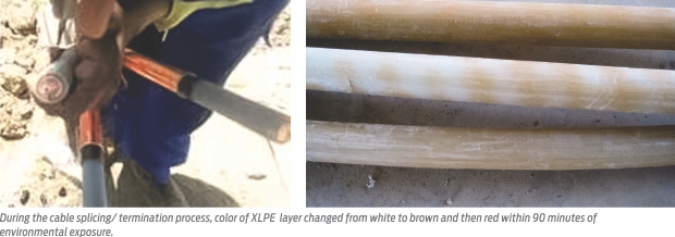
While making splicing /termination of High Voltage XLPE cables, one unusual phenomenon noticed at the surface of XLPE insulation after removal of extruded semiconducting layer. This phenomenon was the spiral ring formation in brown color on XLPE surface. Surprisingly this spiral color changed from light brown to dark brown and then turned reddish when subjected to environmental exposure.
CASE STUDY:
Subject was studied in detail at Research and Development Centre of Havells India Limited and the cause of such XLPE discoloration was established.
TREND OF DISCOLORATION:
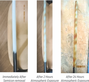 Initially various component/aspects of cable such as quality of XLPE compound, copper tape and processing parameters were suspected as probable reason for such color change/spiral formation but exact cause could not be ascertained after having various study.
FIRST INPUT TO UNDERSTAND THE PHENOMENON:
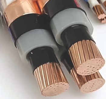
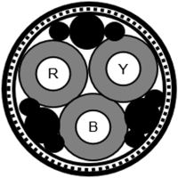
18 cable drums, 500 mts each of size 3c x 150 sqmm 6.35/11 kv were manufactured in a lot. Out of 18 drums, 10 drums were of armored construction and 8 numbers of drums were of unarmored construction.
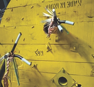 All 18 drums were subjected to routine testing such as AC high voltage test/partial discharge test. Prior to the test, end termination/splicing of each cable ends was prepared as per standard practice as shown in below picture.
All drums passed wth AC high volatge test/partial discharge test and complied to the standard. After AC high voltage/PD test, drums were kept for some time to perform conductor resistance test. Next day, it was noticed that XLPE portion which was exposed to atmosphere during course of time had changed the color from white to brown in spiral form at ends. Surprisingly, this effect happened in only 10 number of cable drums which were of armored construction and there was no any such color change noticed in other cable drums which were of unarmored in construction.
This observation has given basic input to understand the reason behind XLPE discoloration in the cables of armored construction and not with the cables of unarmored in construction.
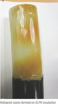 There were two components/ processes which distinguish armored and unarmored construction in this case.
1) In armored cable, armoring was present in form of helically applied galvanized steel flat strips were there while in unarmored cable there was no such armoring.
2) In armored cables, PVC fillers were used to fill the interstices between cores while in case of unarmored cable interstices between cores were filled with PVC applied with extrusion process in pressure.
All raw materials and processes used in both the cable construction (armored and unarmored) were similar except above changes.
FIRST STEP:
Impact of armor was observed by removing the armor portion in armored cables and by applying the electrical potential on the various samples but relation of such of color change could not ascertained.
ACTION PLAN:
We cut the ends of cable drums which had shown color change for further study. Following were the important observations:
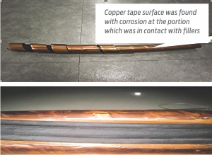
1. Copper tape surface was found with corrosion at the portion which was in contact with fillers
2. While making comparison of corrosion on copper tape as per ASTM copper strip corrosion standard ASTM –D-130/IP-154. Corrosion state found to be moderate.
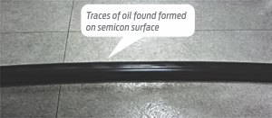
3. Some traces of oil also found on the surface of semicon on insulated core.
SECOND STEP:
PVC fillers which were present in cable with armored construction and not in unarmored construction was taken out from cable assembly for further examination.
IMPORTANT INPUTS ABOUT FILLER MATERIAL:
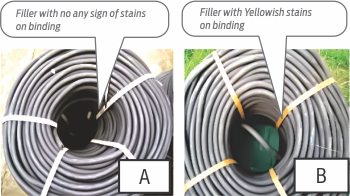
In the stock of PVC fillers which was lying in our RM store, it was noticed that binding strips applied filler coils was tuned yellowish at inner side in some of the coils while others were not having such affect. So it was necessary to find out the reason of Yellowish stain on B filler.
DIAGNOSTIC STUDY:
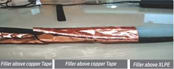
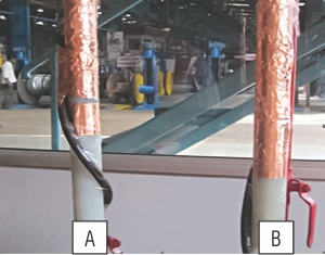
One sample 60cm each cut from A and B coils and applied adjacent to insulated core as per below picture.
Both samples were subjected to environmental exposure for 72 hours.
Observations after environmental exposure for 72 hrs:
1). There was no any affect on the XLPE which was treated with FILLER (A)
2). Yellow stains were noticed over surface of XLPE with filler (B)
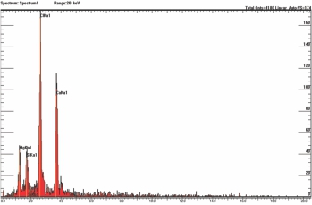
Sample was taken out from Filler (B) for FTIR, Scanning Electron Microscopy/Energy Dispersive X-ray Spectroscopy, and Gas Analysis.
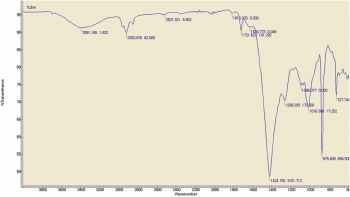
1). Filler(B) material examined for FTIR Analysis: The chemical composition of filler examined for FTIR analysis observation was as below
Observation: The chemical composition of filler material was similar with PVC compound (PVC+TALC+ CaCO3).
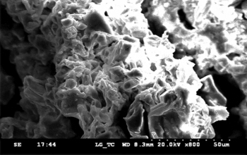
2). Scanning Electron Microscopy/ Energy Dispersive X-ray Spectro-scopy for filler (B)
Observation: Inorganic materials (Cl, Ca, Mg, Si) were detected in filler and they were derived from the PVC, Talc and Calcium carbonate.
Talc: Mg3(OH)2Si4O10
PVC : CH2-CH-Cl
Calcium carbonate: CaCO3
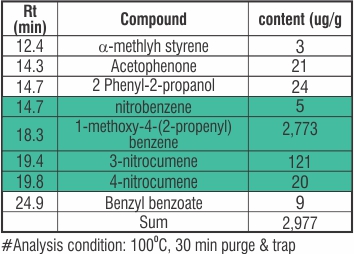
3). Gas Analysis of filler (B): Brown/ yellowish stains which was released at filler (B) checked for Gas Analysis.
GAS Analysis by GC/MSD
Observation: Gas Analysis shows that the main component is 1-methoxy-4-(2-propenyl) and nitro compound.
HOW DISCOLORATION OCCURRED IN SPIRAL FORM OVER XLPE SURFACE:
Traces of liquid released by fillers entered in to the insulation via copper tape in the way of overlap with in laid cable assembly.
CONCLUSION:
1). Release of harmful chemical from filler as Methoxy-4-(2-propenyl) and nitro compound from filler material was responsible for such discolouration.
2). It is not caused by other material like XLPE, semiconducting layer, copper tape or else.
3). Such release of harmful chemical can also affect adjacent component like copper tape.
4). It’s a kind of electrolytic corrosion and presence of absorption current during D.C. application or induced potential rise is accelerating such phenomenon.
5). There was no any electrical degradation noticed due to such discoloration.
OPINION:
Fillers are used in multicore cables to fill the interstices between cores and just to make circular assembly hence no any quality parameters are set in the standard or by manufacturer.
Our study has shown that it is quite desirable to ensure that no any harmful chemical or liquid is released through filler or adjacent layers within cable assembly. As such this release may be of harmful liquid of certain pH and when comes in the contact of metallic sheath and environment, electrolytic corrosion take place and damage the adjacent component of cables.


